I recently came across the “Rat Vac Motion-Sensor Rodent Catching System” by these guys: https://shoprodentstoppers.com/products/rat-vac-motion-sensor-rodent-catching-systems. The idea is really clever. You hook a large wet/dry shop vacuum to the back end and plug the shop vac into the provided outlet. When rat or mouse enters the trap, it senses their presence, turns on the outlet which turns on the vacuum, and the rodent is sucked into the vacuum’s tank, where it drowns in water (or you can make it a live catch trap if you prefer).
The trap was featured in on the Shawn Woods “Mouse Trap Mondays” Youtube channel, and it seems to perform very well: (Rats: https://www.youtube.com/watch?v=Z-c9vFpKgyg, and mice: https://www.youtube.com/watch?v=U4zE8MNz5w8). I have nothing but respect for the inventors, and it takes much effort and expense to take a concept to a sellable product. That said, I think their asking price of around $250 a trap is a bit steep considering that equivalent electronics can be bought in small quantities for about $20 in total. I thought it would be a fun little electronics project to try to create my own version of this trap. That is what I successfully set out to do and document in this post.

For the basic body of the trap I choose a 12 inch piece of 4 inch diameter ABS black plumbing drain pipe. This is relatively inexpensive and seemed like a good working size, though the above mentioned commercial one appears to be using something smaller. The next thing I needed to determine was what electronics I was going to use to detect the presence of a mouse or rat. This actually turned out to be the most painful part of this trap. I originally attempted to use a microwave motion sensor, but it proved to be far too sensitive. I then tried a couple different PIR motion sensors. These failed for a couple different reasons including being too sensitive and suffering from “cheap Chinese electronics” syndrome where they either did not function, were unreliable, or prone to voltage spikes that destroyed my other electronics.
Eventually I realized that what I really needed was not a motion sensor but a proximity sensor of sorts. I started looking into infrared distance sensor circuits. Eventually I settled on an “APDS-9930 ALS IR RGB and Proximity Sensor”.

These run about $1.00 a piece, and can be found in the usual locations. They provide an I2C interface which provides light and proximity sensor readings out to around 10 cm’s. While these ended up working, I’m not sure I would choose them in the future as the Arduino library I found to interact with them is abandoned. In addition, at least one of the ones I ordered was dead on arrival, and they require soldering a jumper on the back if you wish to use the included IR led for proximity readings (which you do). That said, these turned out to be perfect for this project.
After figuring out that you need to solder the jumper on the back (pictured below):

I was able to use this library to reliably get proximity readings: https://github.com/depau/APDS9930.
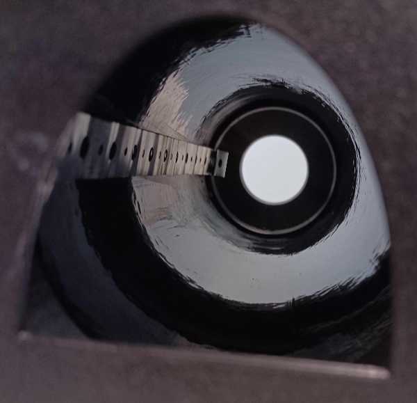
I drilled a 13/32 in. hole approximately 8 in. from the front entrance end of the pipe. By writing a simple test application to give me proximity readings, I was able to verify proper orientation of the sensor and use thick cyanoacrylate glue to hold the sensor in the correct location to detect something in the pipe.
One thing that I quickly discovered with this proximity sensor is that an occasional spurious reading would come through. I could have tossed occasional outliers, but for my purposes, I found that it was fine to simply take roughly ten quick readings and average them. By playing with the resulting configuration, I was able to set a reliable threshold that would not trigger unless something was in the pipe that was at least as large as a small mouse. This worked out well because the sensor was more than capable of detecting the “distance” to the top of a mouse with the sensor located in the “top” of the pipe, while not triggering if the pipe was empty.
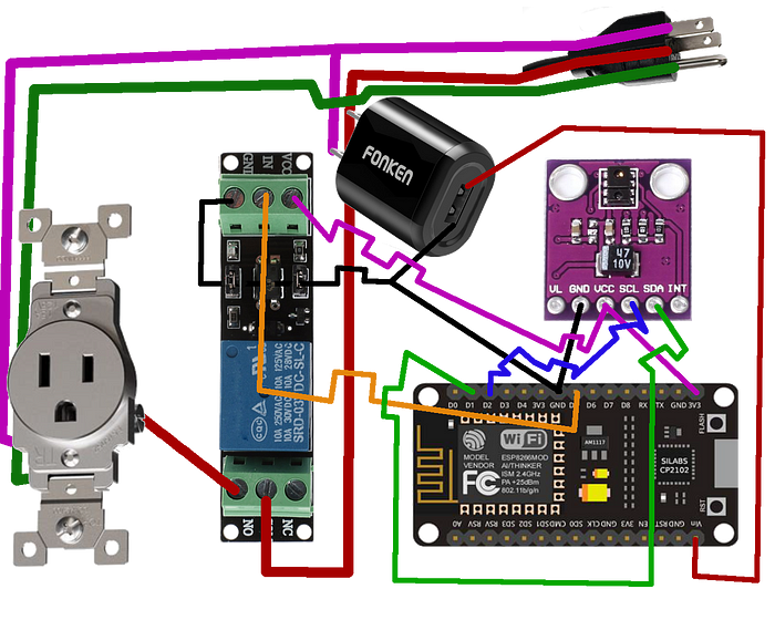
The rest of the circuit (and code are linked below), but are relatively straight forward. I used a NodeMCUv3 board as my MCU. This is because I have a lot of these lying around, they function at 3.3V which is what the sensor uses, and can take 5V on VIN. The MCU triggers a relay board to energize my power outlet. I could have built this circuit up from scratch, but an adequate relay, with optical isolation circuit is effectively a jellybean part and can be had for easily under $2 these days. I just purchased one. The whole diagram of how my circuit is wired is shown below:
I used a slightly modified plastic outlet box from the hardware store to hold the outlet. Due to the depth of this box, I was able to store the switch-mode power supply to power my circuit in the base of this box, as well as the plug and associated wiring. To power the MCU and other low power circuitry, I took a small 5v USB “wall-wart” power supply, and deconstructed it. After soldering leads to the high voltage and low voltage sides, I wrapped the whole thing in wire loom tape to insulate it and glued it to the bottom of my electrical outlet box, which was screwed to my base board.
Some “plumber’s tape” metal strapping was used to secure the pipe to the wooden base, as well as clamping the power cord to the base. The power cord was also purchased at the hardware store. I found that a six foot, 16 AWG cord could be had for quite cheap. Since I only needed the male adapter end and the cord, I purchased a computer power supply cord as it was cheaper than a similarly spec’d extension cord.
At this point, I had a way to detect a mouse and turn on the vacuum, but I needed a way to hook the vacuum hose to the back of my trap, and a way to bait the trap effectively without it being sucked down the vacuum or otherwise interfering with the functionality. I also needed a way to cover and protect the low-power electronics. This gave me an opportunity to hone some 3D modeling and printing skills.
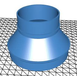
Fresh off my recent success with my TTRPG initiative tracker project and associated 3D modeling, I had enough confidence to attempt this more complicated modeling. For the vacuum adapter side, I decided to go back to OpenSCAD since the adapter design would need a bunch of cone and circular patterns and not much else. Before trying to code up my own model I searched the internet and found this excellent starting point: https://www.thingiverse.com/thing:1246651. I was able to modify this for my purposes. I’ve since found a likely even better solution here (but I didn’t end up using it as I didn’t find it in time): https://gist.github.com/ednisley/5d9bb7fa0518b7cf8cfd9f2e778a9f91
After two slightly bad prints due to tolerance issues, I ended up with something I was happy with. It fit easily into my pipe on one side, with a nice positive-stop lip. I was able to CA glue this into the back of my pipe. I added a ring on the other end that my shop vac pipe could attach snuggly to. If I were to do this again, I would probably add some additional rings for different hose pipes, but this one worked for my purposes and printing already required supports due to the nature of how FDM printing works. With an adapter printed and glued into the back of my pipe, I had a technically functional product, but I didn’t want to stop there.
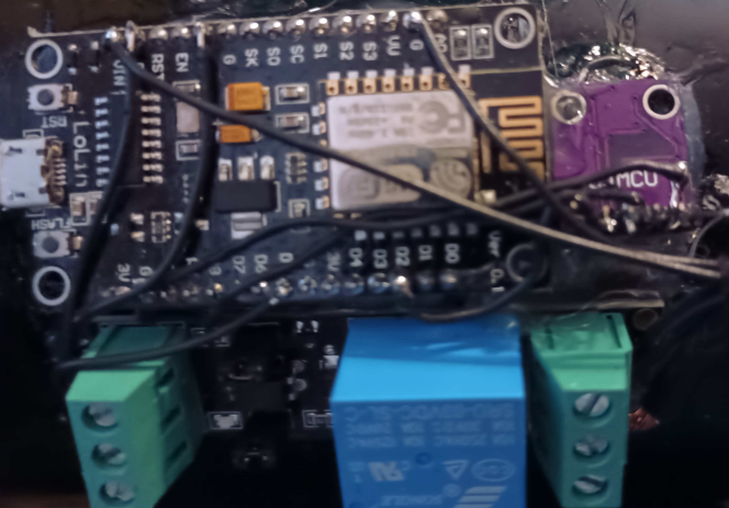
The rest of the things I wished to model certainly could have also been done in OpenSCAD, but seemed to be a bit beyond my geometry skill level. I decided to turn to a more traditional CAD solution. I didn’t need anything too complicated, so I instead opted to try TinkerCAD which is a free, simple CAD modeling solution. It turned out to be almost too simple for my use case, but I was able to produce workable products. I first created a 3mm thick box to cover the low power electronics. I then subtracted a cylinder matching the OD of the ABS pipe from the bottom to create a nice curved shape that would allow me to glue the box over my electronics and proximity sensor. After I was fully happy with my electronics, I used thick CA glue and fixer to affix my MCU and relay circuit to the pipe. Once these dried, I also used CA glue to glue the 3D printed cover over the electronics.
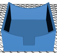
The last thing I wanted to figure out was how to create a nice end cap, and somehow affix bait inside the trap. This seemed like an oversight of the original reference trap, to me. On the one hand, you want a fairly smooth interior so that a rat or mouse has nothing to grab on to when the vacuum starts, on the other, it seemed to me that you wanted some way to affix some bait so as to attract the rodent in the first place, and in such a way that it will not easily be vacuumed up or otherwise interfere with the trap.
After some experimentation, I settled on a notched front end-cap with a pleasing entry design. This cap serves a couple purposes. The first is to slightly restrict the opening so that a mouse or rat cannot easily dive out of the pipe if startled by the vacuum. The idea being that there is a ledge they have to climb over and or navigate around. The other key point is that the restricted entrance will increase air pressure and make it harder for the rodent to escape while the vacuum is building pressure. To affix the end cap, I had to cut a notch in the ABS pipe to accommodate the notch on my model. The last thing I did was to affix a piece of plumber’s tape which rides along the wall on one side. This should stay out of the way of the proximity detector and not provide much of a purchase for a panicked rodent, but the low-profile hook on the end should provide a reasonable bait cup for peanut butter or an almond, and secure it well enough that the vacuum won’t suck it up.

The bait stick is screwed into the end cap and CA glued (I just cut off the excess screw with a Dremel). With the off center weight on the end cap, I ended up needing a couple screws to go through the pipe and into the cap to secure it. I’m not particularly happy with this solution as overtime the threads are likely to wear out, and it is not the most user serviceable. Were I to do a second version, I think I might add threaded fitting to the end of the pipe and print a threaded insert for the end cap.
Since I was using a Wi-Fi capable MCU, I decided to take advantage of this to provide a simple notification system, which I think is kind of clever. Instead of needing internet access or requiring a person to connect to the AP, then visit some website, I instead took advantage of the AP name. When the trap is first plugged in, the MCU will create an access point with the name “Rattrap: 0”. On each subsequent detection and run of the the vacuum, it will update the name. So, on the first trapping, the AP will now be called “Rattrap: 1”. This provides a way to quickly identify that the trap has potentially trapped rodents. If I create additional traps, I might also add a unique identifier.
With the trap was finished, I knew someone that needed it, so I gifted it to them. I’ll have to wait until Spring to know how well it works. I might update this article once I have some “mission” reports.
If you’re interested in trying to build one yourself, or submit a PR with some improvements, please checkout the associated Github: https://github.com/shellster/ShopVacRatTrap
